Logic Max Combi Troubleshooting Manual. Your Ideal Logic Max combi boiler is really easy to take care of, and you’ll find everything you need to know about it right here. Available in outputs of 24kW, 30kW & 35kW, this easy-to-use model benefits from a system filter to keep it in great shape. We’ve got the answers to many of the most asked.. Ideal Logic Plus Combi 24 30 35 Installation and Servicing Manual Instructions. March 14, 2019. Version Download 1645; File Size. Last Updated June 2, 2021; Download. Description. Ideal Logic Plus Combi 24 30 35 Installation and Servicing Manual Instructions. ideal-logic-plus-24-30-35-combi-boiler . GC Number Model Fuel; 47-348-65: Ideal

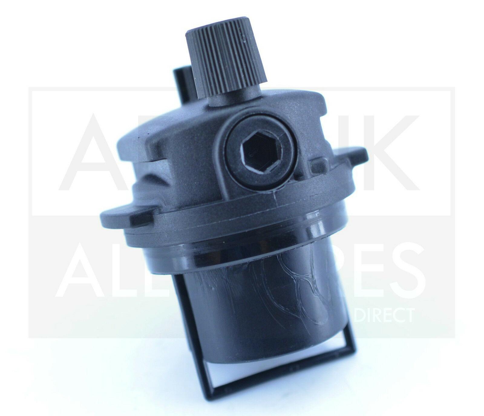
IDEAL LOGIC COMBI 24 30 & 35 EXPANSION VESSEL 175551 & PRV 175413

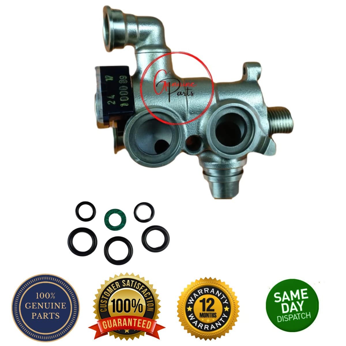
IDEAL LOGIC (+) COMBI 24 30 35 & SYSTEM / HEAT 12 15 18 24 30 GAS VALVE 175562 BoilerRecycling
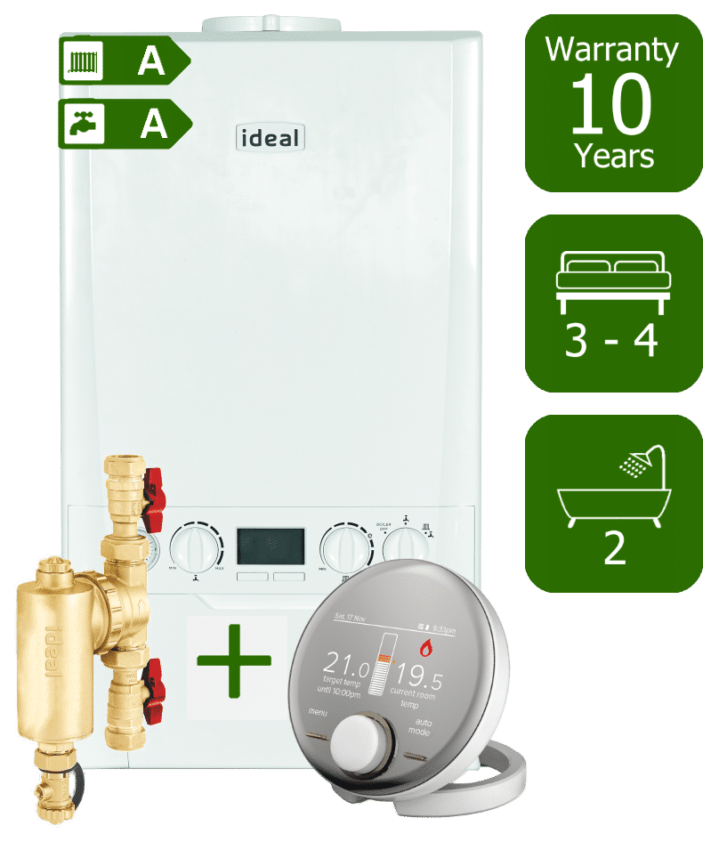
Ideal Logic Max 35kW Combi Boiler Smart Boilers
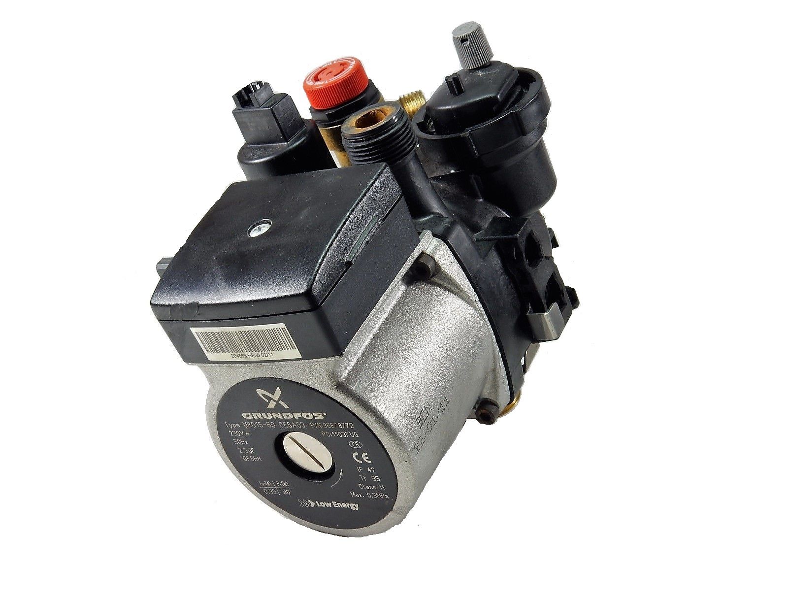
IDEAL LOGIC COMBI 24 / 30 / 35 & SYSTEM 15 / 18 / 24 / 30 COMPLETE PUMP 175555 BoilerRecycling
IDEAL HEATING LOGIC MAX COMBI 2 C24 USER MANUAL Pdf Download ManualsLib

IDEAL LOGIC COMBI & PLUS 24 30 35 & SYSTEM / HEAT 12 15 18 24 30 FAN 175569
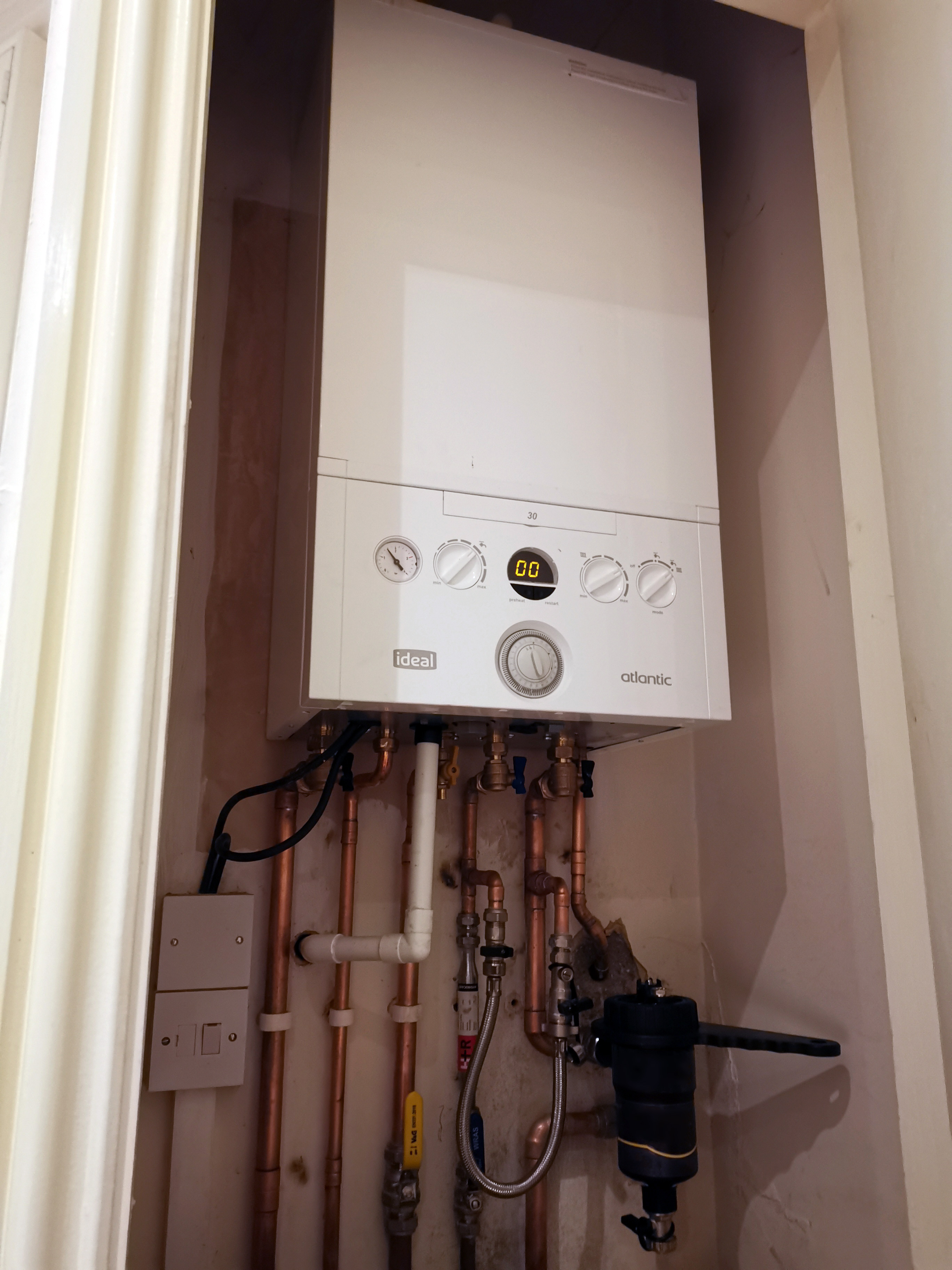
Introducing the Ideal Atlantic Combi Boilers Range Mr Central Heating Blog

Ideal Logic Combi 24 (Gas Management)Diagram Heating Spare Parts
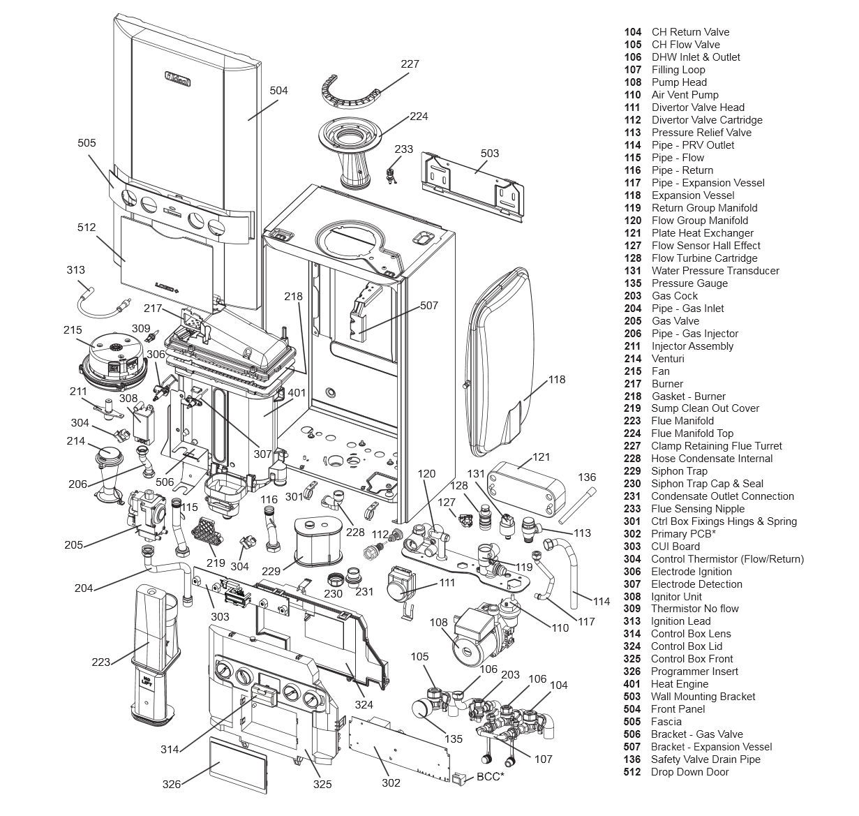
Ideal Boiler & Logic Combi Manuals Parts Lists, Wiring Diagrams, Installation & Service

Ideal Logic Heat 12 15 18 24 30 Installation Servicing Instructions Manual

IDEAL LOGIC COMBI 24 30 35 E24 E30 E35 MAIN PRIMARY PCB 175935 Heating & Catering Parts
IDEAL LOGIC COMBI 35 USER MANUAL Pdf Download ManualsLib
Ideal logic combi 30 24 group kit 175552 with flow sensor 175590 Heating & Catering Parts
Ideal Logic + Combi 24 Manual Plumbase

Ideal Logic + Combi 35 (Gas Management ABK Onwards)Diagram Heating Spare Parts
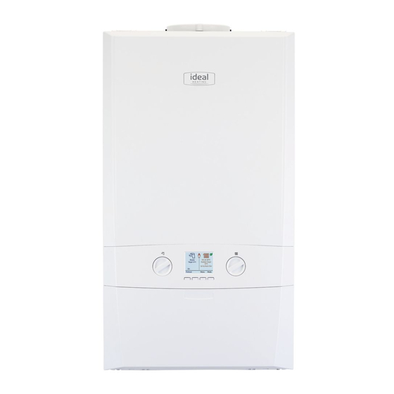
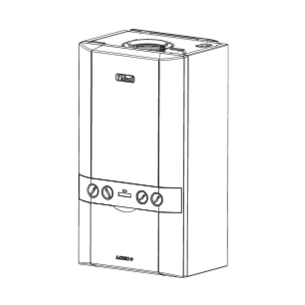
Ideal Logic C24 Combi Boiler Review, Prices & Compare

Ideal Logic 24 Combi Gas Boiler in BurtononTrent, Staffordshire Gumtree
Ideal Logic Combi 24 Review (2023) Warranty & Price of Logic Plus 24 kW
IDEAL LOGIC SYSTEM S 15 18 24 30 IE BOILER PUMP AUTO AIR VENT WITH ORING 176457
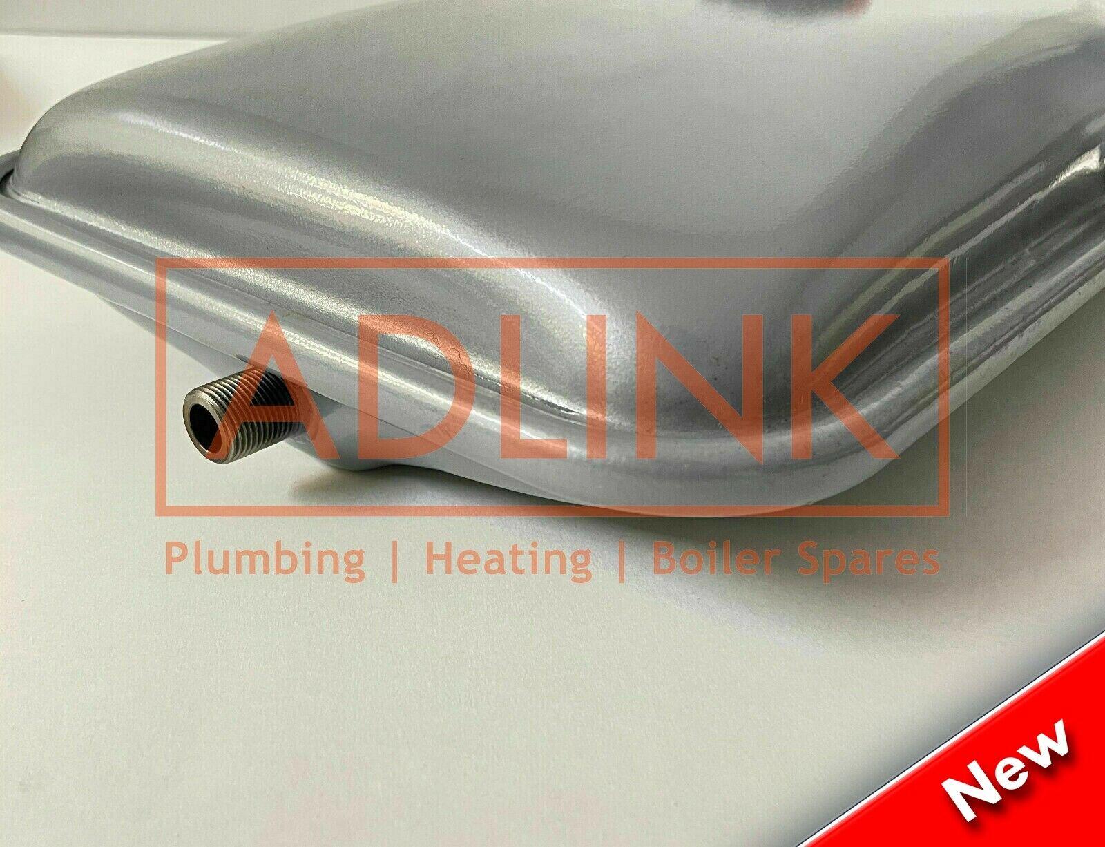
IDEAL LOGIC COMBI 24 30 & 35 EXPANSION VESSEL 175551 & PRV 175413
2 Ideal Logic Combi – User’s Minimum Clearances Clearances of 165mm (6 1/2″) above, 100mm (4″) below, 2.5mm (1/8″) at the sides and 450mm (17 3/4″) at the front of the boiler casing must be allowed for servicing. Bottom clearance Bottom clearance after installation can be reduced to 5mm. This must be obtained with an easily removable panel, to. Your boiler manual is always the first place to look when it comes to getting the most from your central heating system. If you need answers about any of the functions of your Logic Combi ESP1 boiler, Ideal Heating have you covered.. We’ve pulled out key information from the Logic Combi ESP1’s user guide to answer common questions about this popular gas boiler model, which is available in.


 Fanpop")


