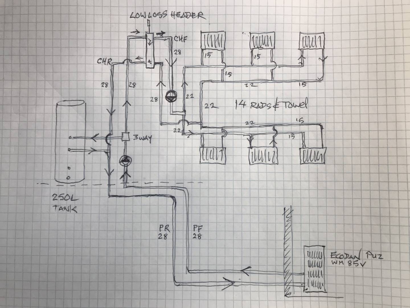
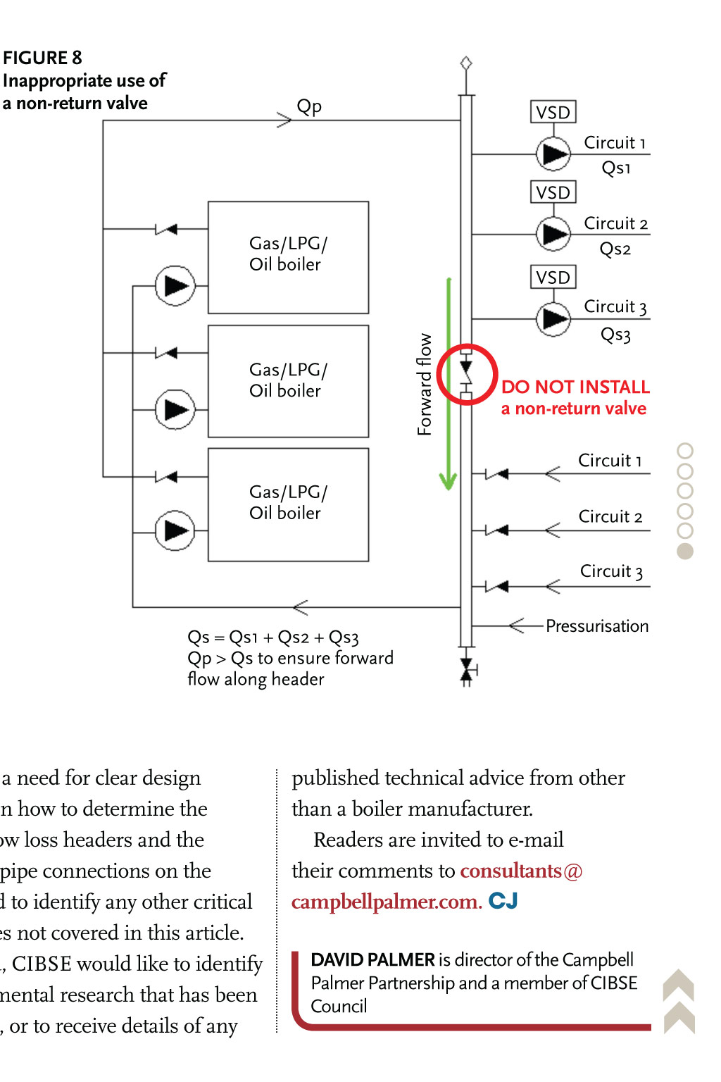
amine the diagram shown below and we will try to perceive what happens as the pumps are activated. The most important thing to consider when measuring interferences between different circuits, is to determine how pressure, net the height difference, varies between the two manifolds. We will refer to this pressure difference as ∆P.. When installing a low-loss header, system mixed supply temperature (T3) must be calculated as follows: The temperature sensor connection [TS] typically located at the top of the low-loss header ensures low return tem-peratures to the boiler at all times and increases opera-tional efficiency. In addition, the low-loss header helps eliminate air and

Guide to low loss headers CIBSE Journal

What is a Low Loss Header? FlexEJ technical guide
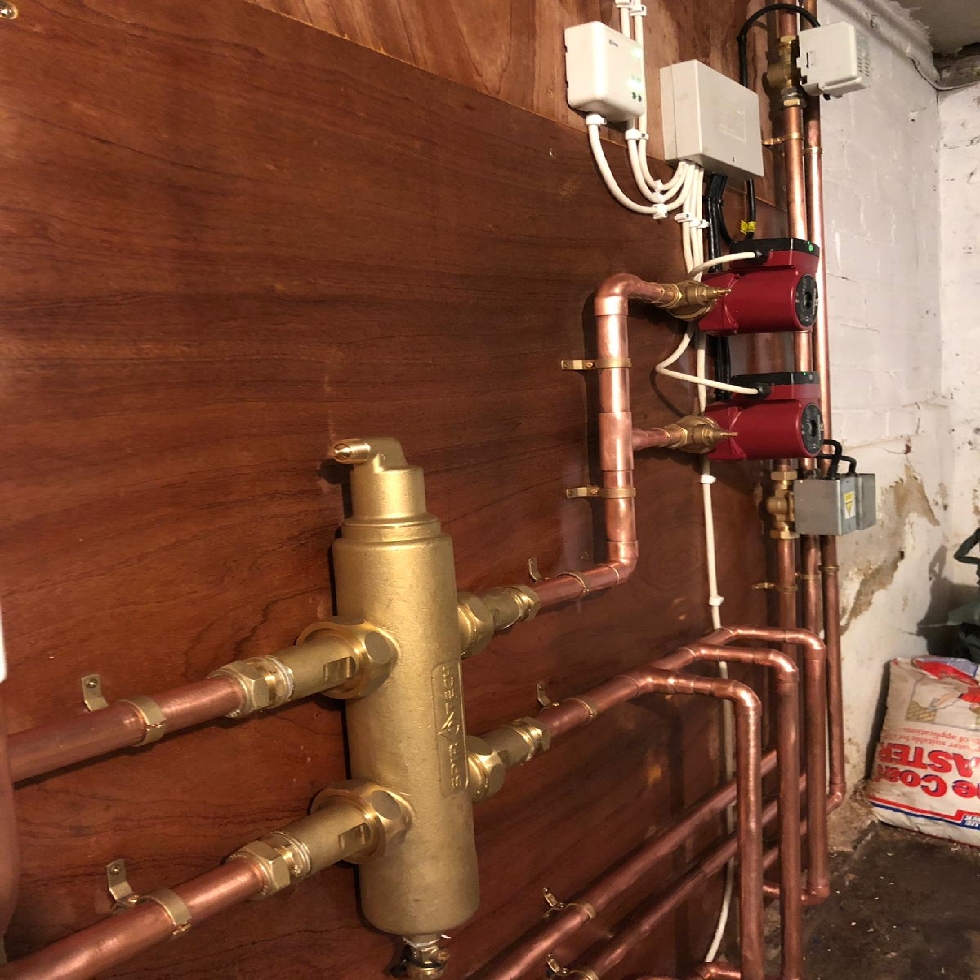
Low loss header upgrade Parkstone Yorkshire
Low Loss Header is losing 1.5c from flow temperature Air Source Heat Pumps (ASHPs) Renewable
Low Loss Header plumbed wrong!? DIYnot Forums
Low loss headers
.JPG)
LowLoss Header am I understanding this correctly? — Heating Help The Wall
Guide to low loss headers CIBSE Journal

Low Loss Headers & Close Coupled T’s Page 2 — Heating Help The Wall

Low Loss Headers & Close Coupled T’s — Heating Help The Wall

“New” Primary Secondary Hydronic Panel using a low loss header! HVAC Mana Tahviyeh مانا تهويه

Primary Tee Direction with Low Loss Header Secondary — Heating Help The Wall
Low loss header upgrade Parkstone Yorkshire
Guide to low loss headers CIBSE Journal
Best Practice Low Loss Headers CIBSE Journal February 2014

Low loss header Hot Water and Central Heating
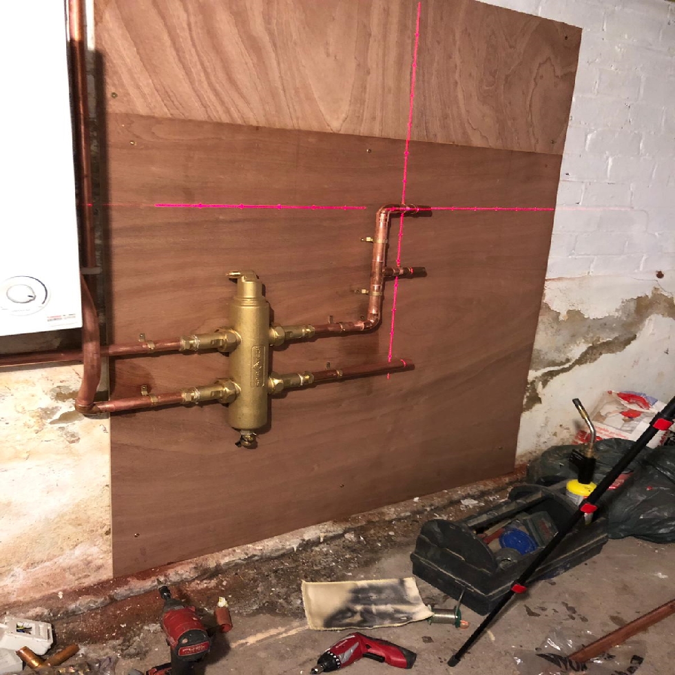
Low loss header upgrade Parkstone Yorkshire

Primary Tee Direction with Low Loss Header Secondary — Heating Help The Wall

low loss header mixed water temperatures by Mike Sammon YouTube
Low loss header upgrade Parkstone Yorkshire
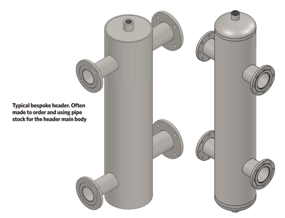
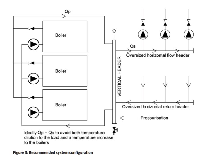
View simple piping and wiring drawings for residential scenarios: Two-sided installation with low-loss header diagram, Two-sided installation with DHW and IBC air handler with modulating fan diagram, Two-sided installation with DHW and buffer tank diagram, Two-sided installation with DHW and radiant floor diagram, Two-boiler installation with DHW and buffer tank loads diagram, Three-load.. The low loss header acts as a ‘hydraulic brake’ to manage the speed of the flow, and only the water/flow required for the secondary circuit (s) is carried through. The low loss header will take any excess capacity from the flow, and return it into the primary circuit. This allows boilers to operate at a constant flow rate in the primary.


 Fanpop")


